In the beginning of 2011, i was asked to create some light effect for electronic music partys. it had to be robust and simple, the budget was just 200 Euros. my first thought was obviously an LED matrix. but as i experienced in my former matrix projects, these things can be expensive. after a short brainstorming, we came up with the following concept: we decided to build single panels that contain five RGB LEDs in a row. these panels can be mounted on the ceiling and are either distributed in the room or combined to form a matrix. the design was kept very simple and therefore cheap, which allowed us to build a few panels with the budget and extend the project if more money is available.
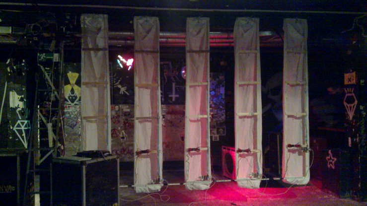
time was short, so we went for five panels to end up with a 5*5 matrix at the first party. we bought slats, stapled them together and ended up with ladder-like constructs that were 3.3 m long and 0.4 m wide. some fabric was used as a diffusor. an ATmega168 and some transistors on a breadboard control the five LEDs and the thing looked like this:
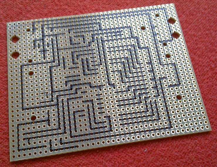
as you can see, the angle of radiation of the LEDs seperates the singe ‘cells’, making it possible to display clear ‘pixel’ images later on. since a breadboard is not the most robust solution for electronics and manufacturing PCBs would have been to time-consuming/expensive, i used perfboard and throughhole components. i routed the board in Cadsoft Eagle and used a CNC mill with a pen as a plotter to draw the traces onto the boards before soldering. this made it easy to reproduce them and place the mounting holes. no more messing around with mirrored Eagle printouts and forgotten traces. optimized like that, soldering went pretty fast, about an hour for a complete board.
so what’s on that board? as the brain, i still use the ATmega168. ULN2001A darlington arrays drive the LEDs and a 1489N RS232 receiver changes the +-12V signal to 0-5V. the voltage regulation is handled by a 7805, dirty but inexpensive. the complete board costs around 10 Euros. as connectors for the power supply, i chose 4 way MOLEX power connectors because they are cheap, robust and reverse polarity protected. for the data line, standard SUB-D9 connectors are used. the boards are designed to be daisychained, so power/data in on one side and power/data out on the other side.
power is supplied by an old ATX PSU. i use the 12V line and regulate down to 5V on the single boards. this is done to overcome voltage drops when using a long power line and many boards.
the data stream that controls the panels is generated by an old laptop running some python scriptage on a linux system.
all panels share the same RS232 line. this is possible because they only receive. each panel has it’s own address and can thereby be controlled individually, so it does not matter if you want to control one or fifty panels. the firmware on the panels handles the datastream, generates the PWMs via binary coded modulation and performs a gamma correction.
the protocol for data transmission is rather simple:
'A',address,15 bytes of data (5xRGB)
represents a data package for one panel, 17 bytes in total.
here’s a video of the finished five-panel, 3*3 m matrix:
the panels so far survived 3 partys, rough handling and beeing stored under bad conditions.
so yes, this is the billionth LED matrix, but this time, it’s large scale and really cheap, easy to build and makes a cool illumination for partys. and it always surprises me how you can still amaze people with a bunch of blinking LEDs.
specs in short:
* panel is 3.30m x 0.4m
* costs for each panel: 25 Euros
* 5x superflux RGB LED per panel
* RS232-bus
* 24 bit color depth
* ~80 FPS @ 5 panels in a matrix
feel free to download the source files including firmware sources, example python script and eagle files.
if you have any questions, please do comment.


[…] The budget for the project wasn’t much at 200 Euros, but he did manage to build decent 5×5 RGB LED matrix that is fully controllable by a […]
[…] parties. The budget for the project wasn’t much at 200 Euros, but he did manage to build decent 5×5 RGB LED matrix that is fully controllable by a […]
[…] parties. The budget for the project wasn’t much at 200 Euros, but he did manage to build decent 5×5 RGB LED matrix that is fully controllable by a […]
I love the CNC routing the conduits with a pen as a layout tool for soldering. Great idea. This is a well executed product and looks cool. I would recommend plastic rounded tiles instead of fabric, but that’s just a personal suggestion.
Why not use an LED driver, like the MAX6969, that can drive more current? Costs a little more, but is very consistent in light output.
Good job,
Mike
The use of a microcontroller offers much more freedom. I can access the module via the serial port, a MAX6969 (correct me if I’m wrong) would require some sort of converter between the serial port of the laptop and the driver, which would probably be a microcontroller. So the component costs would rise again. But you’re right, a dedicated LED driver would be the most elegant way to control LEDs.
I too have been looking to build one of these for an up coming party. I was looking at mimicking an already existing RGB LED wall that is sold at lighting shops…basically, a black cloth with an LED every 6 inches. I figured i’d make an 8’x8′ panel, with 16 LEDs in each column. I was under the impression that you could use PWM to control the individual LEDs in each column, however, this is a very intriguing way to go about it. please feel free to email me, as I’d like to pick your brain on a coupe things if you don’t mind. I’ve been checking out all these different matrices and i just don’t know which method to go with. I’m gone as far as purchasing some darlington arrays already, but that was before i’ve seen dozens of other examples, so i’m now spoiled for choice. Anyhow, great work and i hope to hear from you.
[…] The budget for the project wasn’t much at 200 Euros, but he did manage to build decent 5×5 RGB LED matrix that is fully controllable by a […]
I want to see the reverse side of a soldered board!
))) Picture of bottom side (((
This is the first prototype. Note that the FAT traces are GND/VCC. The wires are not a fix but planed. 🙂
[…] The budget for the project wasn’t much at 200 Euros, but he did manage to build decent 5×5 RGB LED matrix that is fully controllable by a […]
Wow thats realy cool
[…] in a former similar project, i used a CNC mill to plot the traces onto the […]
[…] 200mA each. we had a bunch of ULN2803 available in the lab, which already served me well in other LED projects. i designed a board that was easy to manufacture, single sided and chainable. it is called […]